About ConsoleCast
Why ConsoleCast?
Serial communication is still a popular way of communication between all kinds of different devices. Throughout history where computers or data related equipment is used, serial communication has been used in many different forms. There are many protocols and interfaces. Nowadays the USB standard is used in most consumer devices but RS232 is also still used with network- or other professional equipment. Although RS232 is a trusty standard in the world of data communication, it's getting harder to use because of the lack of old-style serial ports on modern computers. The use of adapters or cables with built-in adapters is common to circumvent this problem.
ConsoleCast falls into the category of adapters for serial communication. However, it has some advantages:
- Wireless
- Platform independant
- Software (terminal) embedded
- RS232 and USB OTG connectivity
- Multi-user
- Open source
ConsoleCast incorporates an ESP32S2 chip module to enable wireless communication. The S2 variant of the ESP32 also has on-board USB capabilities which can be used for USB host functionality. Although RS232 ports are still popular, there are some devices using a Communications Device Class (CDC) USB port. These ports expect a host (computer) to connect directly to it. ConsoleCast has circuitry for configuring its USB-C port as a host device port. This means that ConsoleCast can brigde this type of connection wireless over WIFI. RS232 datalink is handled by a standard RS232 chip using the correct signal voltage levels. Low capacitance ESD protection is provided to protect the ConsoleCast circuitry.
The provided example firmware implements a use-case where ConsoleCast can be accessed using a browser. This makes ConsoleCast platform independant. Also there is no additional software like a Terminal Emulator needed, the software is embedded. ConsoleCast is running its own webserver which can be accessed over a secure HTTPS link. ConsoleCast can act as an Access Point itself or can connect to any other Access Point to become part of a network.
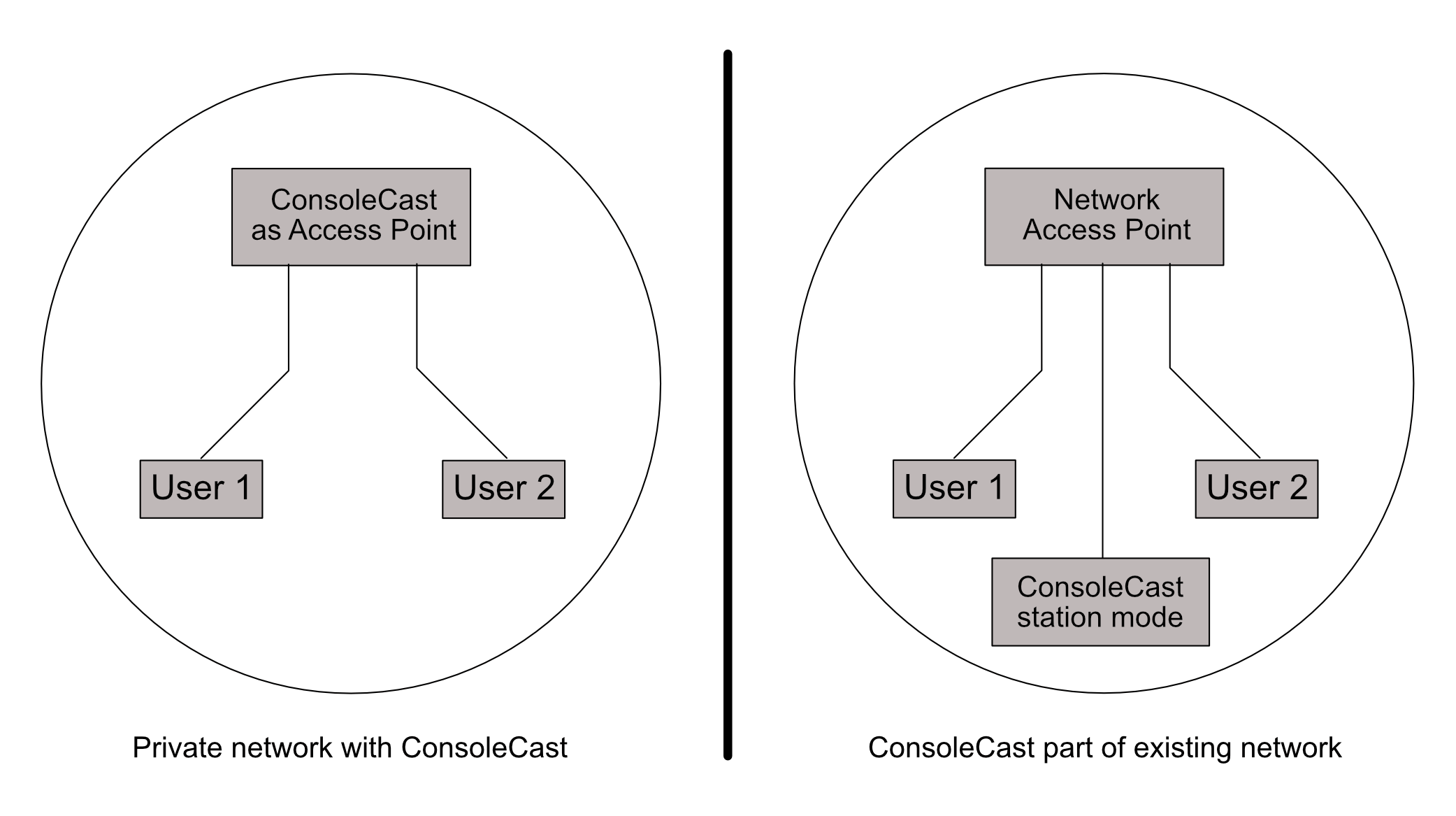
In both configuration multiple users (by default max 2) can be connected to ConsoleCast but there's only one terminal session with a device connected to ConsoleCast. That means that both users are working in the same session on the same device.
Open Source
Although ConsoleCast can be used out-of-the-box using the example firmware, we strongly encourage users to edit, enhance or replace this basic firmware with specific functionality. In this sense, ConsoleCast is like any other development board, it is fully open for programming and experimenting. For this reason we not only publish the example firmware but also the schematic files on Github. The example firmware is using the ESP-IDF framework, but you're not bound to that (although we didn't explore other options like Arduino, CircuitPython or MicroPython for ESP32).
Powering ConsoleCast
ConsoleCast is utalizing a 18650 Li-Ion cell as its stand-alone power source. You need an unprotected flat top 18650 battery (65mm). Other types can be to long for the battery holder. ConsoleCast has battery protection on-board. Also a decent capacity (around 3000 mAh) will keep your ConsoleCast going for quite a while. Be sure to insert the battery the right way, polarity is clearly indicated. Inserting the battery the wrong way can damage the device. There is automatic power switching circuitry for selecting external power when the USB port is connected to an external power source. When not connected to USB power, the battery will be used (if available). The battery is needed when using ConsoleCast in USB host mode (for CDC ports) as the USB-C port is then used to communicate with the device. In this setup ConsoleCast acts as a host and must provide power to the CDC device. It's important to have the battery (fully) charged as there has to be a voltage provided by ConsoleCast when acting as a host (close to 5V). This is done using a booster circuit. The 18650 voltage is boosted to around 5V but when the battery voltage drops too low this will fail to reach the 5V needed.
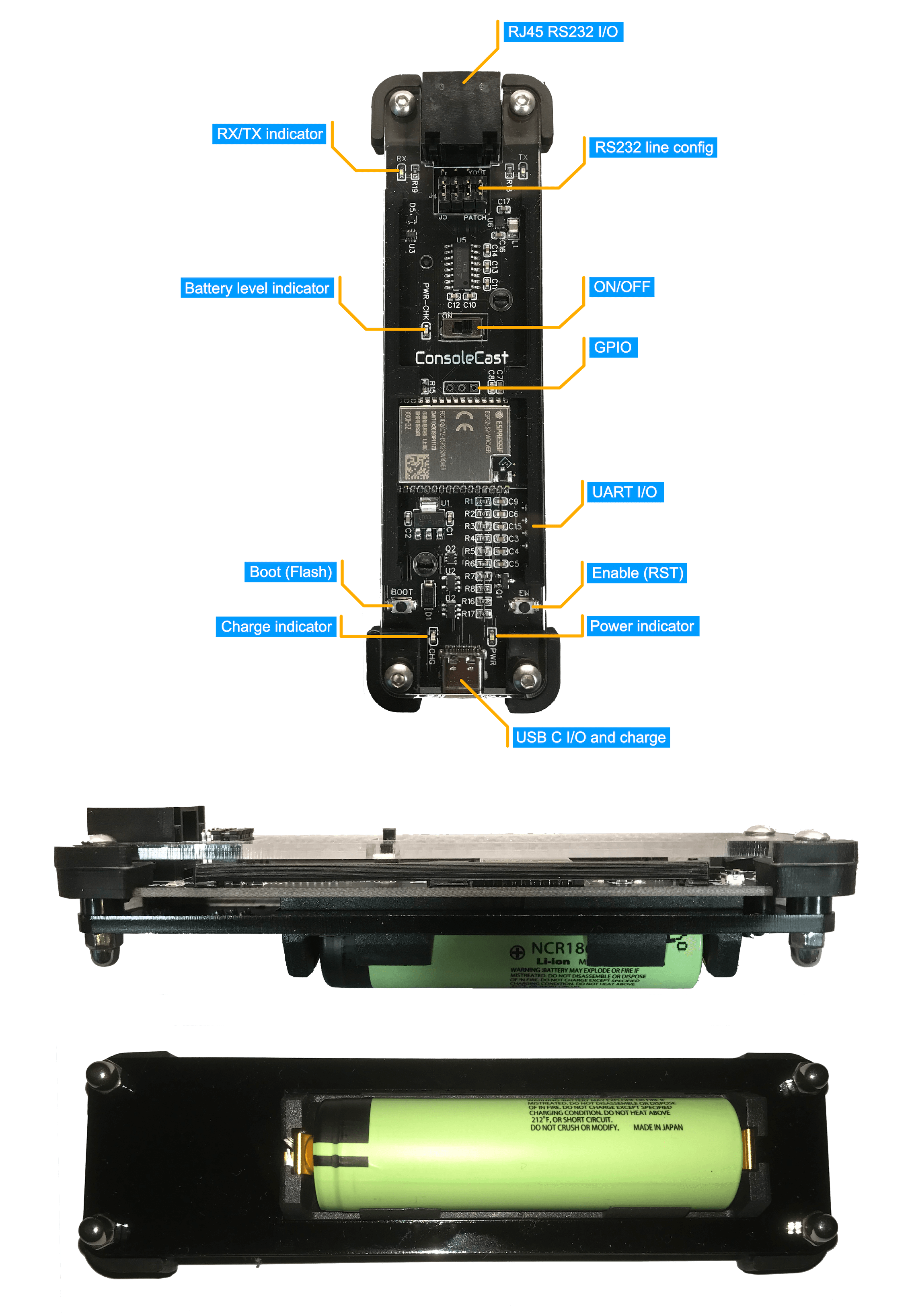
Also, ConsoleCast has an on-board charging circuit. For charging the battery, the USB-C should be connected to an USB charger or computer. The power indicator lights up (green) when external power is provided and the Charge indicator will light up (orange) when charging, until the battery is fully charged. The charging circuitry uses a very conservative charging current. This is done for safety reasons but it means that charging can take several hours. To save power, there is no always-on power indicator when powered by battery only (the green power indicator is for extarnal power). Instead there is a power check indicator (labeled PWR-CHK for Power Check) near the on/off switch that lights up briefly when switching on. The more empty the battery, the longer it lights up and when the battery is almost fully drained, it stays on. It's hard to tell when the battery voltage is too low for CDC host operation. That can vary from device to device (the device CDC port ConsoleCast is connected to). So, it's better to keep the battery topped up or to keep a spare when using CDC port access regulary.
Addendum:
As pointed out by TheHWcave in his video on ConsoleCast, the RC constant of the PWR-CHK circuit needs modification to be more useful. This will not be adjusted for the current batch of boards (because the PCB layout will have to change). We have to experiment with component values to find a suitable solution. This will probably be an extra resistor in series with C6 (see schematic on Github) to slow down the charging time.
It will be of no influence of the rest of the functionality of ConsoleCast. It just means you have no good indication of the battery level and should be aware of using a charged battery yourself. Especially when using the USB CDC connectivity.
Serial port
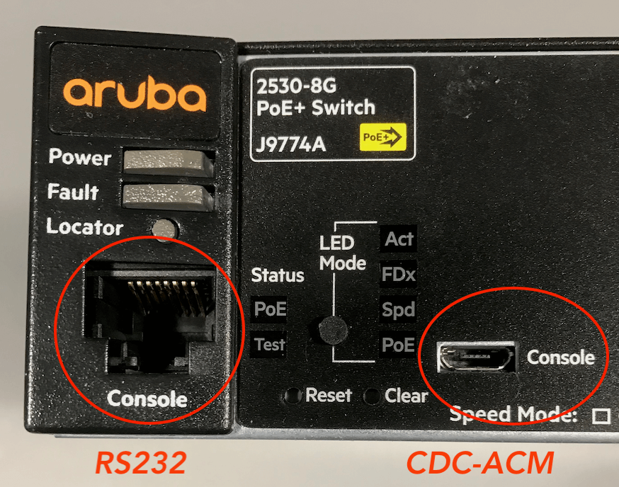
When using the USB-C port for connecting to a device you just have to be sure the device port actually is a CDC (ACM) port expecting to be connected directly to a host computer. Sometimes devices have USB type ports that are used for different purposes and are not in fact CDC ports. Currently many devices have micro USB ports for CDC functionality (see picture above). You need a USB-C to micro USB cable to connect to it. The cable needs to be capable of handling data (not power only).
The RJ45 connector on ConsoleCast is for RS232 data traffic. Most network equipment has a console port also consisting of a RJ45 port type. You just need a short patch cable to connect. This can be a normal network patch cable used to connect switch ports or when preferred you can use a Yost type cable. The RJ45 port of ConsoleCast can be configured either way, for patch or Yost cable use. This is done using a jumper array.
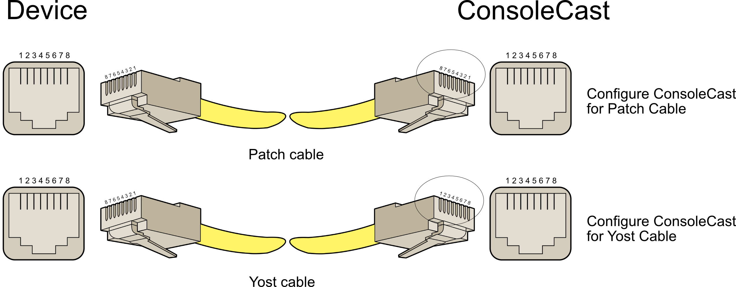
The PCB mask shows at which side the jumpers should go. Most times all jumpers are in line, but for an exotic use case also other combinations could be used. All they do is connecting the data lines to different connector pins.
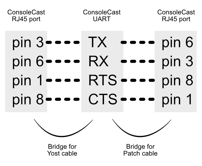
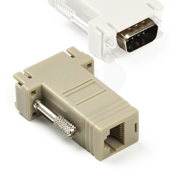
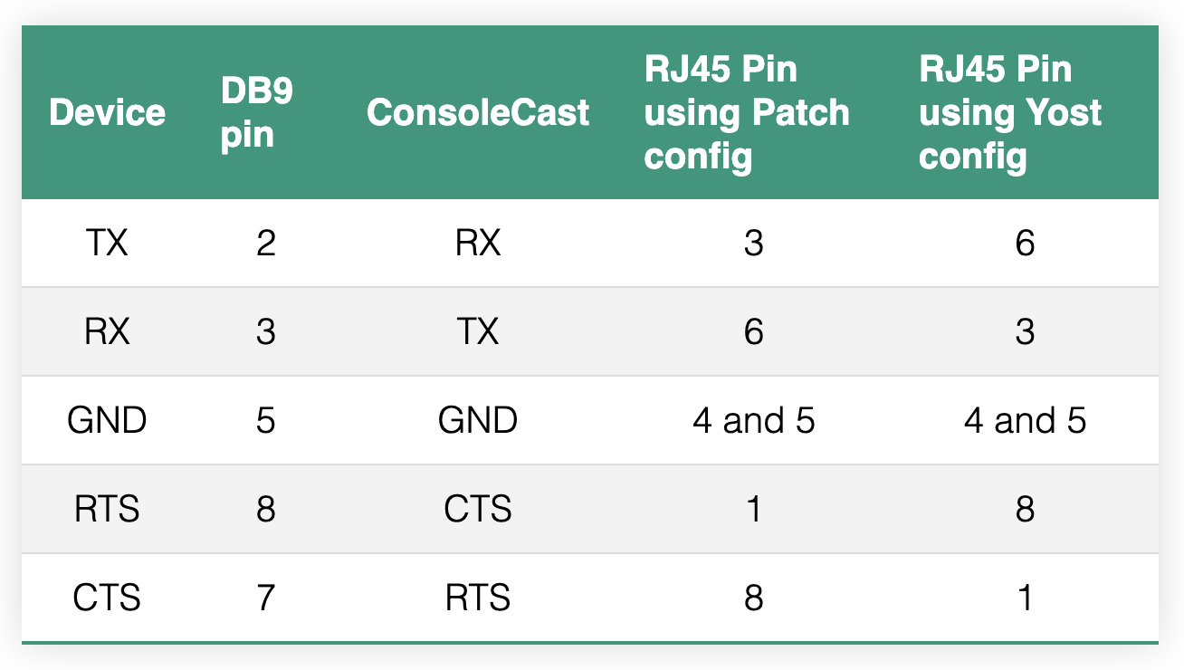
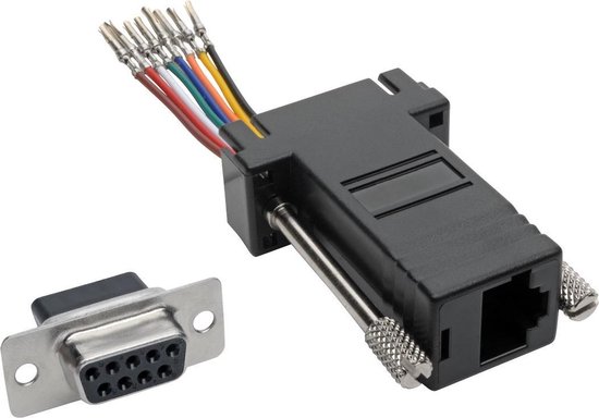
When a device doesn't have an RJ45 connector for serial communication, you would use an adapter (cable). For instance if a device like a power supply has a DB9 connector for serial communication you can use a DB9 to RJ45 adapter. Some are even configurable. RS232 based pinouts are fairly standard but you can check the manual of your device. In general you connect ConsoleCast TX pin to the device RX pin, RX to TX, CTS to RTS and RTS to CTX.
Configure an adapter
ConsoleCast uses 4 data-lines TX, RX, RTS and CTS plus GND (signal ground). In many cases the RTS/CTS are not even used by devices. In these cases only TX, RX and GND are used. Dependant on the Patch/Yost configuration (jumper settings) the pinout of the RJ45 is as follows:
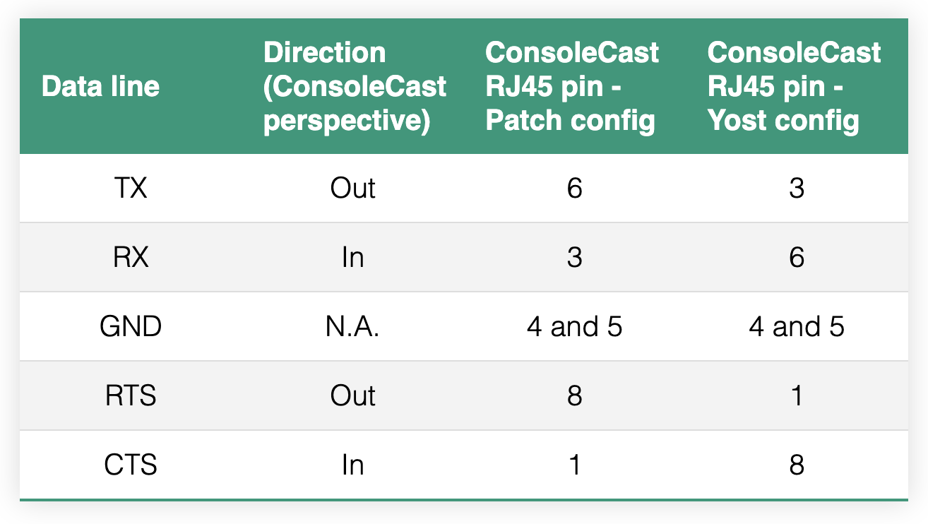
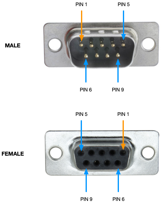
When using a configurable connector (see image below) you can route the four data lines as needed. You should check your device specifications for the DB9 pinout on your device. The table below shows the normal pinout of a standard DB9 serial connector:
Examples
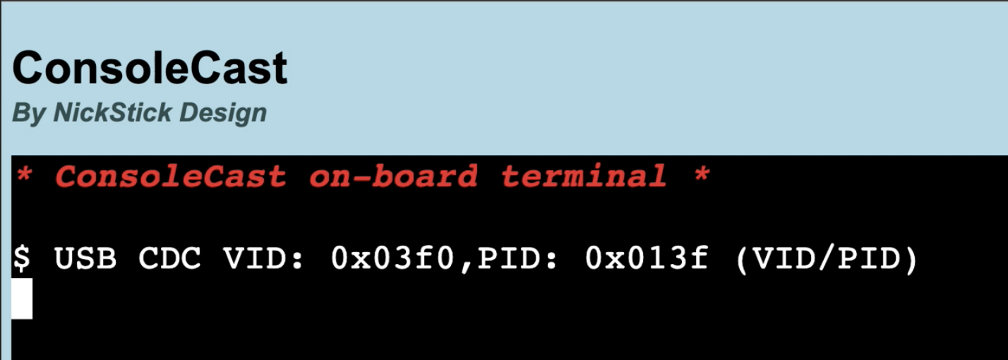
When using ConsoleCast in serial mode with an Aruba 2530 / HP J9774A switch you can use a normal patch cable and set the four jumpers in the Patch (default) position. With this particular device you can also connect using a USB cable (see screenshot).

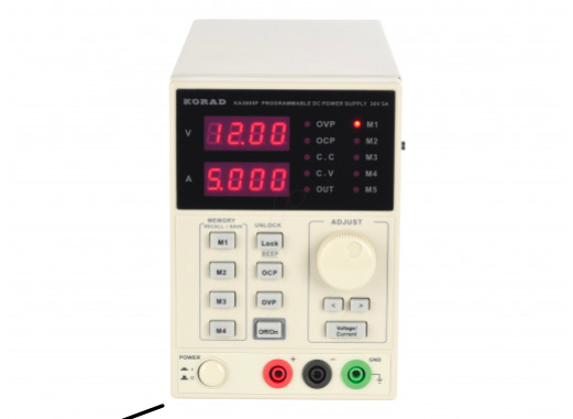
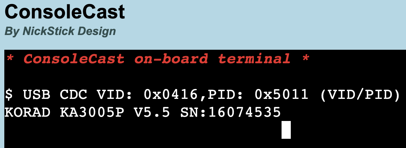
For a Korad KA3005P power supply (serial port) you can use a normal patch cable (jumpers in Patch position) with a Male DB9 adapter having DB9-pin 2 (device TX) to RJ45-pin 3 (ConsoleCast RX), DB9-pin 3 (device RX) to RJ45-pin 6 (ConsoleCast TX) and DB9-pin 5 (device GND) to RJ45-pin 4 or 5 (both are GND on ConsoleCast). Also with this device you can use a USB cable (see screenshot).
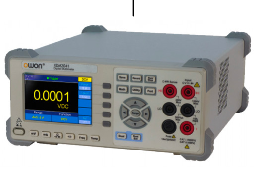
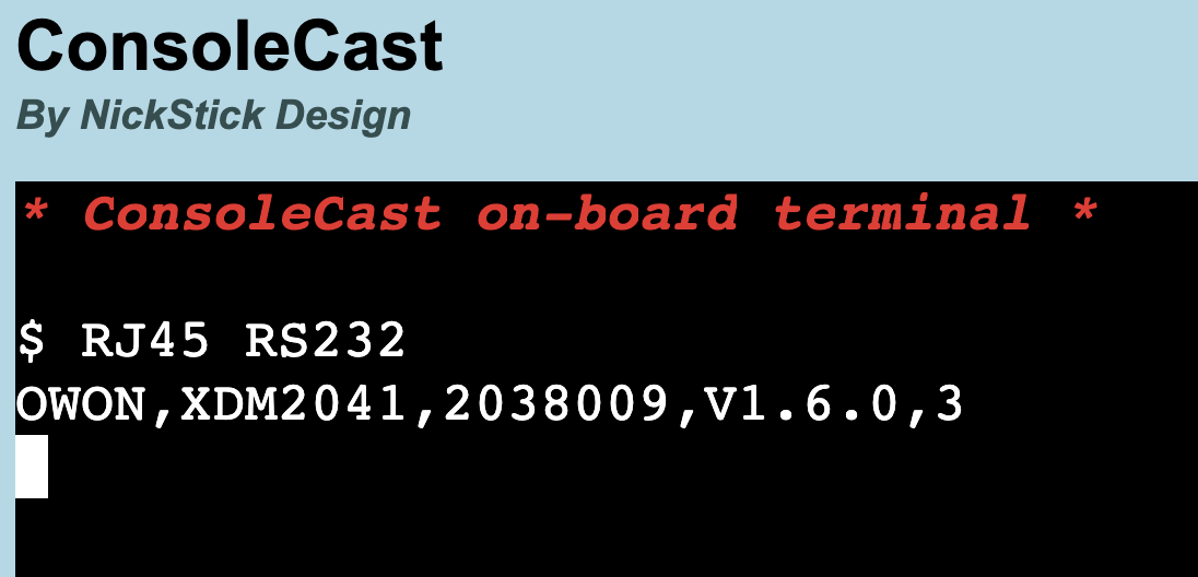
For an OWON XDM2041 Multimeter you can use the same configuration but you will need a a Female DB9 adapter or a small gender changer, as the Owon uses a Male DB9 on the device. The Owon (this particular device) does not have a USB connector.
GPIO
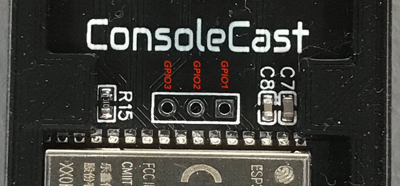
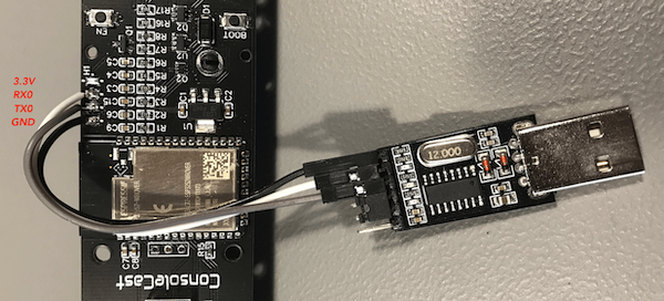
GPIO1, 2 and 3 of the ESP32-S2 on ConsoleCast are broken out for testing or special requirements. Also RX0, TX0, VDD33 and GND are available at the edge of the PCB. You can attach an external UART to USB module for programming and monitoring. It's an extra option as the programming can be done over the on-board USB-C connector also. However at the time of this writing there seems to be a problem with monitoring over the built-in USB (please see Github issue for details).
